
Wrist Mounted CD Launcher (04/18/2025)
Introduction
As an engineer – and, most importantly, a male – I’ve always had the strong urge to build things that shoot. As a kid, I would make these mini BB guns using mechanical pencils and rubber bands. In high school, I made my YouTube debut with a video titled Motorized Nerf Gun. Now, I think it’s time to take things up a notch. After staring at a CD one day, I had the idea to create a CD launcher. After all, they would make excellent projectiles because they’re lightweight, thin, and disc-shaped.
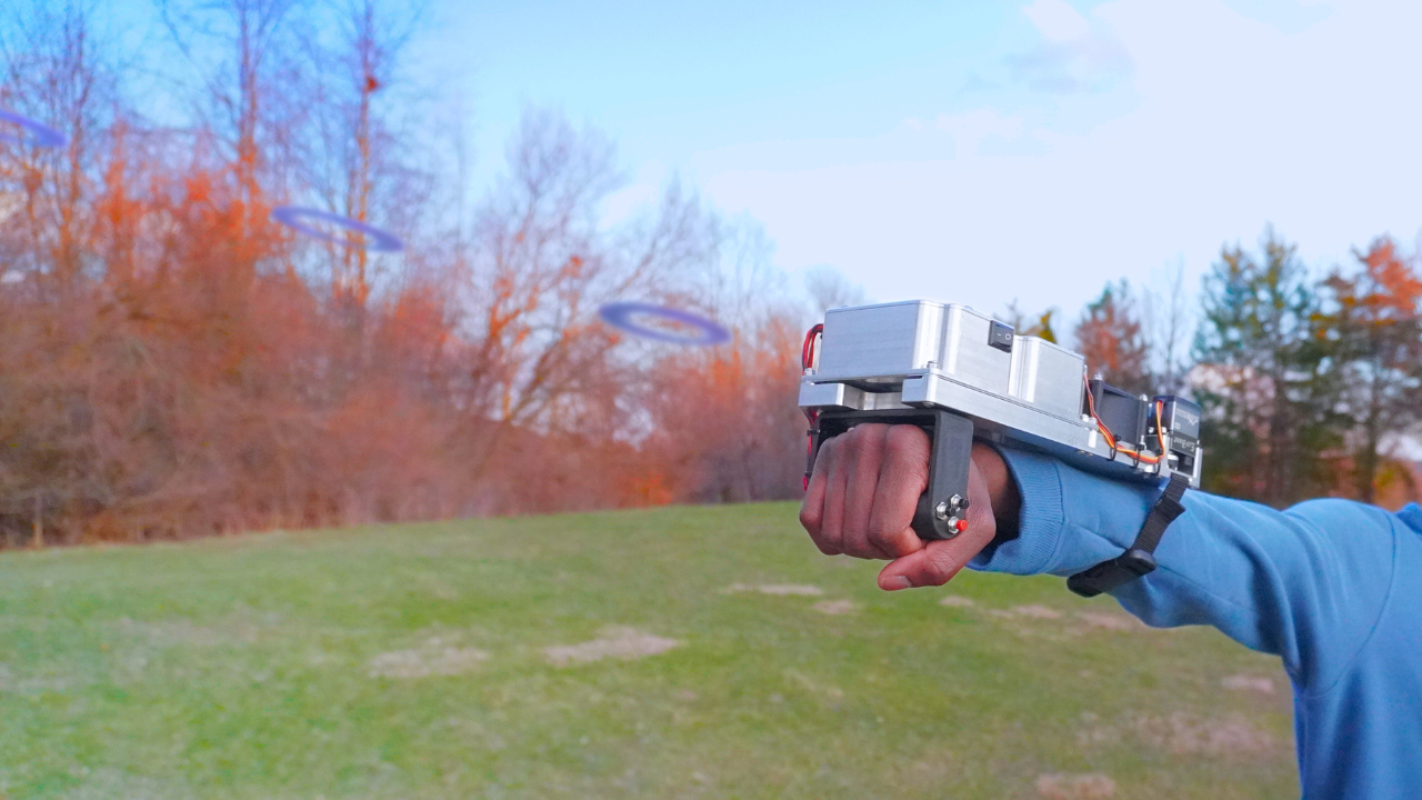
I’m not the first to come up with the idea of a CD launcher. The game Far Cry 6 has a weapon called Discos Locos that shoots CDs. The Hacksmith built a real version of this weapon in a video titled RAPID-FIRE CD LAUNCHER from FAR CRY 6 using brushless motors and flywheels. Lastly, a video from 2013 titled CD Gun – which I believe started it all – used an angle grinder to shoot CDs with an immense amount of power. Taking inspiration from all of these launchers, I decided to make my own with a unique spin. Instead of a CD gun, I wanted to build a wrist mounted CD launcher which, in my opinion, is much cooler. A wrist mounted device also posed some unique design challenges relating to weight and compactness. For example, instead of the standard size CDs I opted to use mini CDs, which are much harder to find and much more expensive. After finishing this project, I can confidently say that I have built the world’s first wrist mounted CD launcher. The device can shoot CDs at 33 mph, has a magazine with a capacity of 25 CDs, and can rapid fire at a rate of 5 CDs per second.

Flywheels
The heart of the CD launcher is the flywheels. A flywheel is a mechanical device (often disc shaped) used to store and often release rotational energy. Flywheels are commonly used in competitive robotics, from VEX to FRC to Battle Bots. Flywheel shooters, also used in competitive robotics, are a common projectile launching method as they can shoot projectiles rapidly, with high velocity, and in a controllable manner. A flywheel shooter operates by spinning a flywheel at a high speed and then sliding a projectile onto the path of the flywheel’s radius, at which point the projectile is launched. Though the concept is simple, in practice, a flywheel shooter has several variables to consider. The first two things that I wanted to figure out were what motor to use to spin the flywheel and what diameter to make the flywheel. My main constraints when making these selections were size and mass, as this device would need to fit on my wrist and be easily held. In keeping with this theme, I wanted a small, light, and fast motor, so a brushless drone motor just seemed to make the most sense. I eventually settled on the Emax RSIII 2207 2100KV, mainly because my local drone store had it. It’s able to achieve a top speed of around 40,000 RPM. To control the motor, I used a 35A ESC.
Determining the diameter of the flywheel required some calculations. The diameter of a flywheel is directly proportional to the exit velocity of the projectile. My goal was to find the biggest flywheel diameter that I could have without making the flywheel too big. To get an Idea of how small I could make the diameter, I decided to use the CD Gun video as a reference. Given that the Harbor Freight Angle Grinder used in the video spins at around 11,000 RPM and given that the diameter of the flywheel is around 4.5” (≈ 115 mm), the estimated exit velocity of the CD in the video is 65.83 m/s. Knowing this as well as the speed of my brushless motor (40,000 RPM), I calculated a diameter of 31.43 mm. This is the diameter that my flywheel should be in order to achieve the same exit velocity as the CD Gun video. I ultimately decided to go slightly higher with a diameter of 50 mm. The aforementioned calculations are explicitly shown below. Keep in mind that these calculations are very rough. The main assumption that I used to simplify calculations is that there is no energy lost in the flywheel-CD system. In reality, this couldn’t be further from the truth, which is why I overcompensated by increasing the diameter to 50 mm. Another limitation/flaw in my calculations, that I didnt realize at the time, is that the motors never ran at the full 40,000 RPM. These calculations, therefore, rely on the most optimistic scenario possible, which makes them very misleading. The main benefit of them is that they gave me a starting point.

Once I settled on a motor and flywheel diameter, I moved on to designing the shape of the flywheel. This directly affects the amount of energy that the flywheel can store. The equation for the stored energy of a flywheel is shown below.

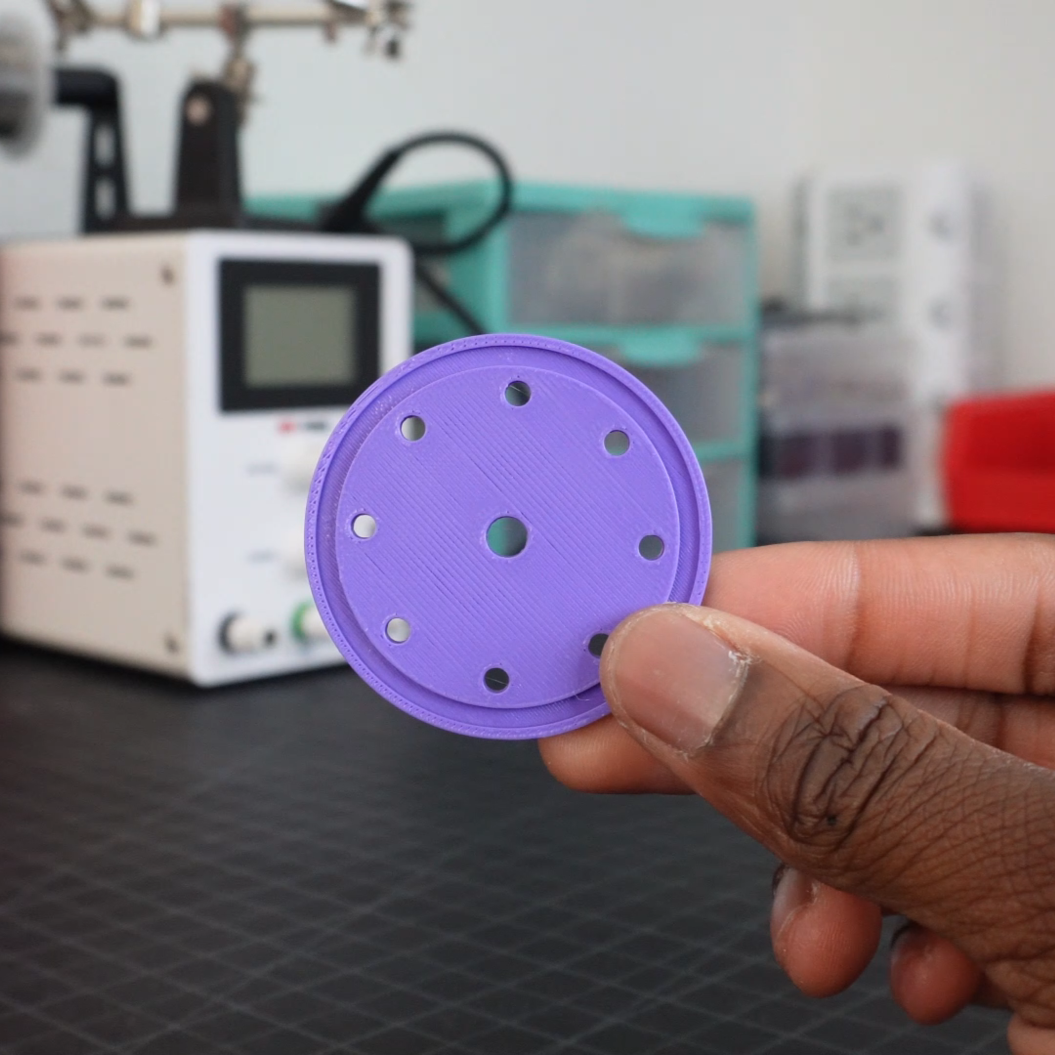
The energy stored in a flywheel is directly proportional to the consistency of the shooter. In other words, A flywheel that stores more energy won’t slow down as much in between shots. As shown in the equation, the energy stored by the flywheel is also directly proportional to the moment of inertia of the flywheel, or the flywheel’s resistance to rotational motion. The moment of inertia of the flywheel is dependent on the flywheel’s shape, axis of rotation, mass, and radius. To determine the flywheel’s shape, I designed a couple of flywheels and chose the one with the highest moment of inertia. It just so happens that the fully solid flywheel provided the highest moment of inertia. The three flywheel designs are shown below as well as their masses and moments of inertia that I measured in CAD.
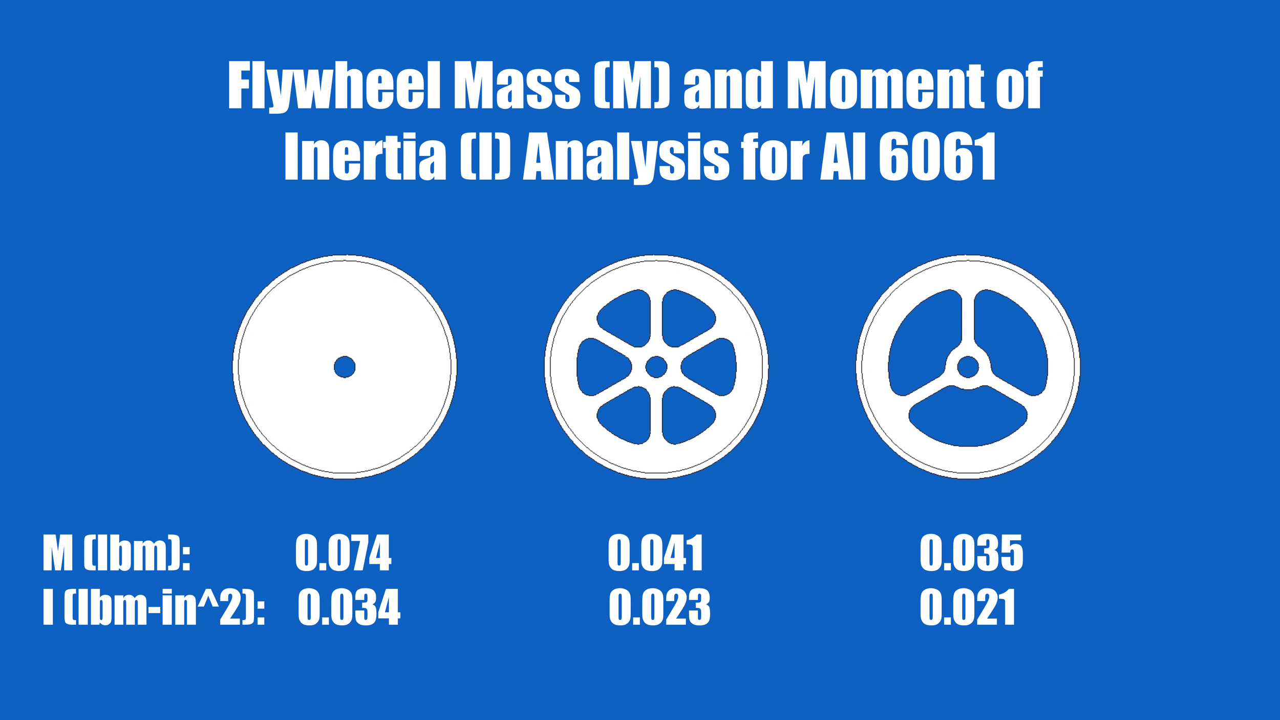
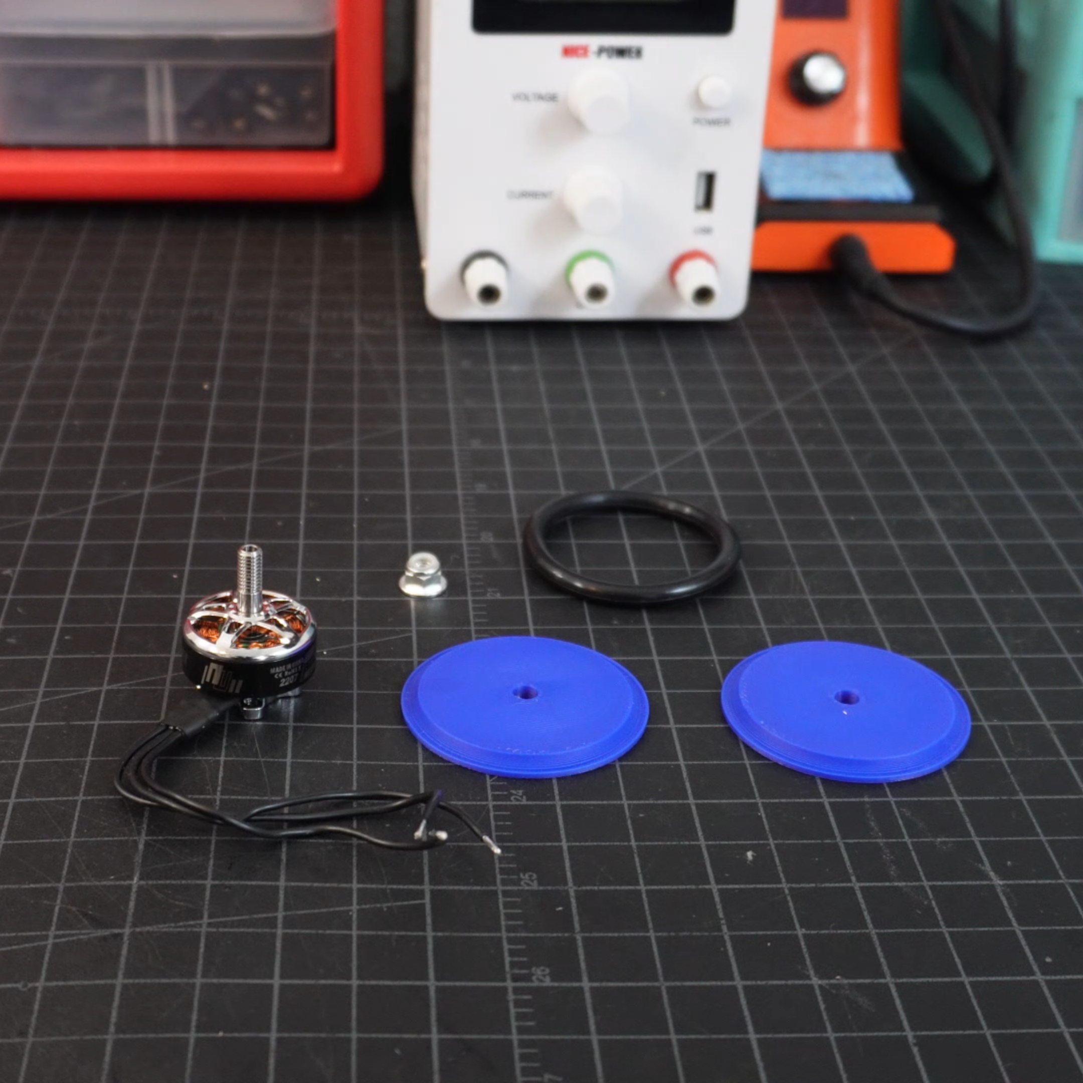
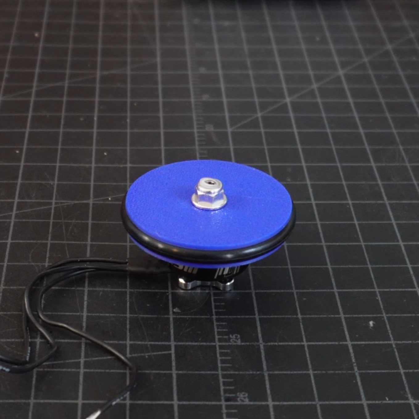
You’ll notice that the mass and moment of inertia analysis was done for aluminum 6061. While I prototyped the shooter in PLA, the plan was to ultimately use aluminum since a denser material means a heavier flywheel and a greater moment of inertia. With a flywheel design selected, the next step was to build it and then test it at high speed. The flywheel is a two-part design that squeezes an O-ring in between, as shown in the images below. The O-ring is meant to grip the CDs. To test the flywheel, I attached it to the brushless motor and slowly accelerated the motor to 100% throttle. During this process, something quite interesting happened. The immense amount of centrifugal force generated by the high RPM flywheel caused the O-ring to rip out of the flywheel and fly across my room. After some prototyping, I found a solution. I added a lip to the outer diameter of the flywheel halves and added screws to the outer radius of the flywheel as shown in the images below. The lip allowed the flywheel to pinch the O-Ring tightly at its outer radius. The screws allowed the two flywheel halves to squeeze together and create a ton of clamping force to further retain the O-ring. As an added benefit, the screws also increased the moment of inertia of the flywheel.
Single-Stage Shooter
After finding a suitable flywheel design, I moved on to building a simple single-stage flywheel shooter. I positioned the flywheel to only contact the outer radius of the CD in order to impart a spin on it. I also made the flywheel angled so that it could drive the CD into a rubber strip to prevent slipping and allow rolling. This further helped generate spin. Imparting a spin on the CD is extremely important because of the concept of gyroscopic stability. This is the same principle that allows a spinning top to stay upright. Spinning projectiles have greater stability than non-spinning ones and can be shot more accurately. The obvious tradeoff here is that the CD has to expend energy to spin that it would otherwise use to travel straight. Considering the drastic differences in accuracy between the spinning and non-spinning CDs, I would say that this tradeoff is well worth it. The spacing between the flywheel and the CD was an interesting design challenge that I had to tackle. If the flywheel is too far from the CD, then the CD won’t be shot with a lot of power. If the flywheel is too close to the CD, then the flywheel will get stuck on the CD. Considering that the CD is only 1.2mm thick, I found the search for optimal spacing to be quite a tedious process. I printed many different motor stands, each one being 0.1 mm off in height from the previous. Eventually, I got a little smart and decided to print a single motor stand and then use thin washers to offset the height by fractions of a millimeter.
To test the shooter, I started the motor at a low throttle level (15%) and shot a CD through my ballistic chronograph, which measured its speed. I did this five times at the given throttle level to calculate an average speed value. I then increased the throttle level by 5% and repeated the process until I reached 50% throttle. The resulting data (shown below) shows that the CD speed began to drop at higher throttle levels. This seemed counterintuitive. The speed of the motor should be directly proportional to the speed of the CD, right? While this relationship is generally true, it’s not always true. At extremely high speeds, the flywheel will slip past the CD, preventing all of its energy from transferring to the CD and causing a drop in speed. This, therefore, implies the existence of an optimal throttle level that can shoot the CD the fastest. Looking at the data, this was exactly right. I found the optimal throttle level to be 25%. At this throttle level the average CD speed was 7.88 m/s.


Double-Stage Shooter
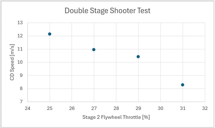
The single-stage shooter worked well, but I wanted to achieve even higher CD speeds. To accomplish this, I decided to make a double-stage shooter. The idea was to shoot the CD at the optimal throttle level in the first stage and then further accelerate the CD with the second stage. Incrementally transferring energy to the CD in two stages prevents the slippage problem that I ran into with just a single stage. Designing the double-stage shooter was as simple as increasing the length of the runway and adding another flywheel. The only important thing here is that you need to ensure there is enough space between both stages so that there is never a point where the CD is in contact with both flywheels. After building the double-stage shooter, I had two questions. First, how fast should the second stage throttle be? Second, how much faster can I get the CD to shoot compared to the single-stage shooter? Both of these questions were answered experimentally. The testing process was similar to that of the single-stage shooter. The throttle of the first stage remained at a constant 25% throughout testing since this is the first stage’s optimal throttle level. I initially set the second-stage flywheel to 25% throttle as well. I then shot the CD 5 times while making sure to measure its speed each time. I then increased the throttle of the second stage shooter by 2% and repeated the process until I reached 31% throttle. The data showed a strange trend. The fastest CD speed was achieved when the second-stage throttle was 25%. This didn’t make sense because 25% is the optimal throttle level of the first stage. It is expected that the second stage should be able to achieve its fastest speed when the second stage spins faster than the first. Though this was odd, I still noticed a huge increase in the CDs speed with the double-stage shooter as compared to the single-stage shooter. With both stages at 25% throttle, the CD averaged a speed of 12.14 m/s, which is about 1.54x the faster than the highest average speed of the single-stage shooter. I hypothesize that although the two stages spun at the same speed, the second stage was able to restore any energy that wasn’t fully transferred to the CD in the first stage due to things like slipping, friction, etc.. Now, theoretically, adding more flywheel stages should further accelerate the CD, but I neglected to do this due to the aforementioned size constraints.
Magazine and Feeder
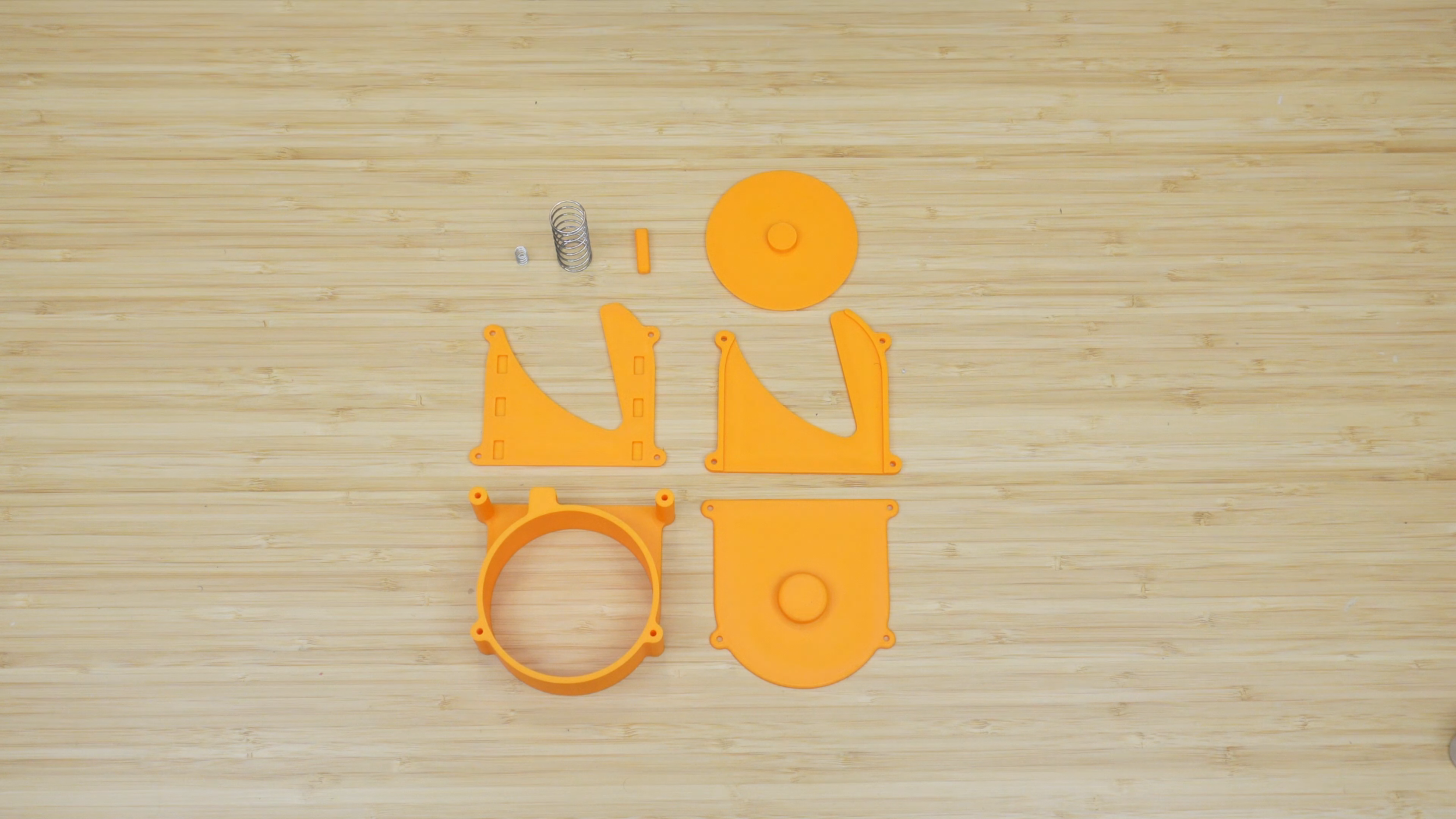
With the shooting mechanism of the CD launcher figured out, I moved on to designing a magazine and feeder for the launcher. The goal of the magazine was to be able to quickly reload CDs into the launcher as opposed to having to manually reload them. The simplest magazine design would be to stack a bunch of CDs in a cylinder and rely on gravity to push the stack down when one CD is shot. While this could work, there are two potential issues. Firstly, what happens if I rotate the launcher upside down? Now, gravity is working against the stack, preventing the next CD from being shot. A similar issue also occurs if the launcher is rotated sideways. A simple magazine only works if the launcher stays upright. The second issue is that there is nothing stopping the next CD from slipping out and being shot unexpectedly if the launcher is tilted forward or shaken violently. To fix both of these issues, I designed a more elaborate magazine than a simple cylinder. The design uses 6x 3D printed parts, 2x springs, 4x screws, and 6x N52 grade magnets. The design was inspired by the Nerf guns I used to play with as a kid. The magazines for those guns used a spring to push the bullets to the top so that after one was shot, the next one was immediately ready to be shot. The magazine could also retain the bullets, so that they wouldn’t unexpectedly fall out and be shot. My design does precisely the same thing. The big spring is used to press the stack of CDs down, and the small spring pushes a stopper to prevent the next CD from unexpectedly being shot. All of the parts stack together like a sandwich. The 6 magnets are encased in the bottom housing. They’re meant to attach the CD to the launcher, which also has 6 magnets. I found this to be a simpler solution to retaining the magazine instead of some kind of mechanical latch. The magazine holds 25 CDs at a time. To reload the magazine, you simply slide each CD in through the entrance. The CDs can also be removed by pushing them from the back and out through the entrance.

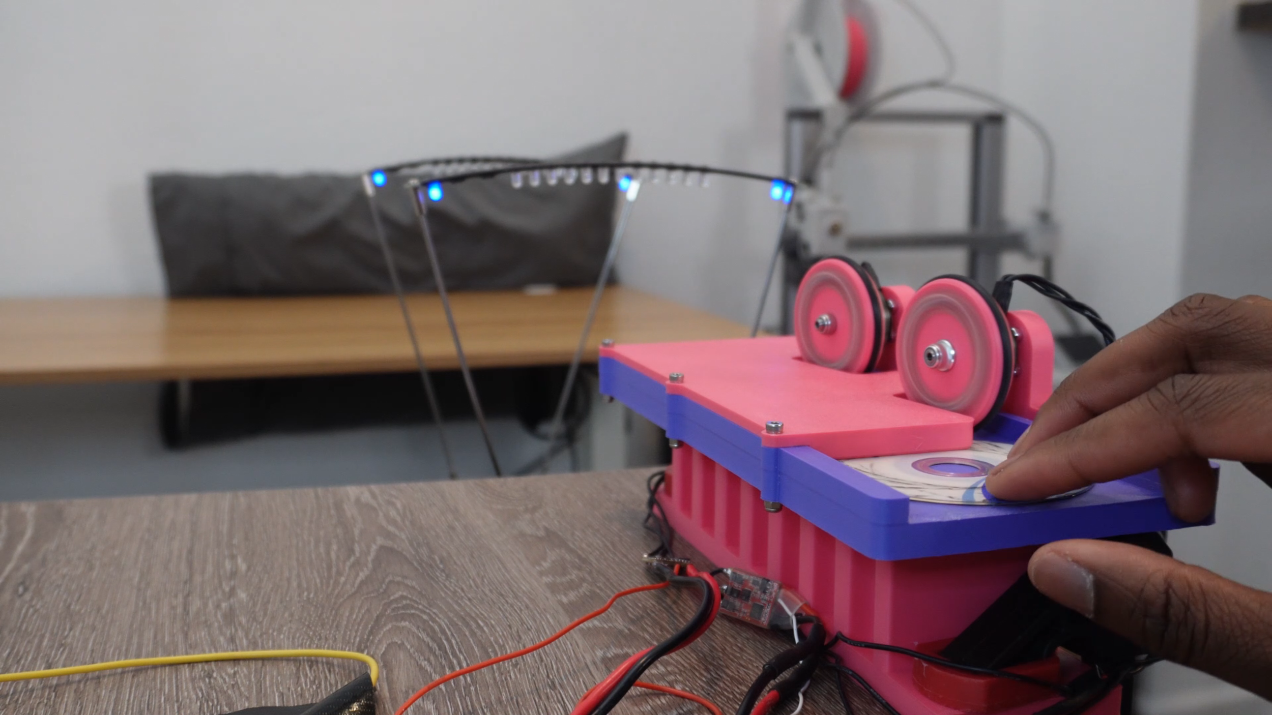
The goal of the feeder mechanism was to be able to dispense the CDs from the magazine and into the launcher as fast as possible. To do this, I used a JX CLS6336HV 35Kg Servo. These servos are extremely fast. A couple of years ago, I used one to make Electronic Wolverine Claws, and its performance speaks for itself. I designed a servo arm to allow the servo to push the CDs out from the magazine. The servo arm was designed to be as long as possible while still being within the size constraints of the device. From dynamics, we know that the farther away a point on a circle is from the circle’s center, the faster the point’s linear velocity is. In other words, a longer servo arm ensures a faster firing rate. To test the feeder and magazine combo I built a mini single-stage test shooter shown below. The goal of this mini shooter was to simply test the firing rate of the feeder without concern for the CD’s speed or the accuracy of each shot, hence the single stage and short runway. After testing the feeder, I found the maximum reliable firing rate of the shooter to be 5 CDs per second which means it fires a CD every 200 milliseconds, which also means it can empty out an entire magazine in 5 short seconds.
Prototyping the Full Launcher
The next step in the project was to combine all three subsystems (the double-stage flywheel shooter, the magazine, and the feeder mechanism) into one wrist mounted CD launcher. The brain of the device is a Teensy 4.0. The handle on the device has 3 pushbuttons that turn the motors on/off, shoot a single CD (single shot), and continuously shoot CDs (burst shot). Everything is powered by a 6S 1000mAh LiPo battery. This battery is nice and small, fitting well with the compactness theme. When the motors are turned on, the motors accelerate at a constant rate to their respective throttle levels over a duration of 3 seconds. This was done to prevent the ESCs from drawing a ton of current at once. Looking back, this probably wasn’t super necessary, considering that I’m operating at relatively low throttle levels. After testing to make sure that the full launcher worked, I decided to do one last set of testing since the double-stage shooter results didn’t make much sense. I ran precisely the same exact test that I ran before and got much better results. The data showed a similar trend to the single-stage shooter test, albeit much more scattered. Initially, the throttle level directly caused a faster CD. Eventually, increasing the throttle level had diminishing and eventually negative effects on the CD’s speed. From the data, I was able to find that the optimal second-stage flywheel throttle was 31%, which produced an average CD speed of 14.62 m/s (32.7 mph). This is 1.2x the CD speed of the previous double-stage shooter test. I’m still not exactly sure what went wrong with that previous test to cause a strictly negative relationship between throttle level and CD speed. This is especially mysterious considering that I did multiple trials for each throttle level and took the average of them. My best guess is that the motors were continuously being overworked, so the more testing I did, the worse the performance I got. When doing testing on this 3D printed prototype, I made sure to wait for the motors to cool down in between trials.


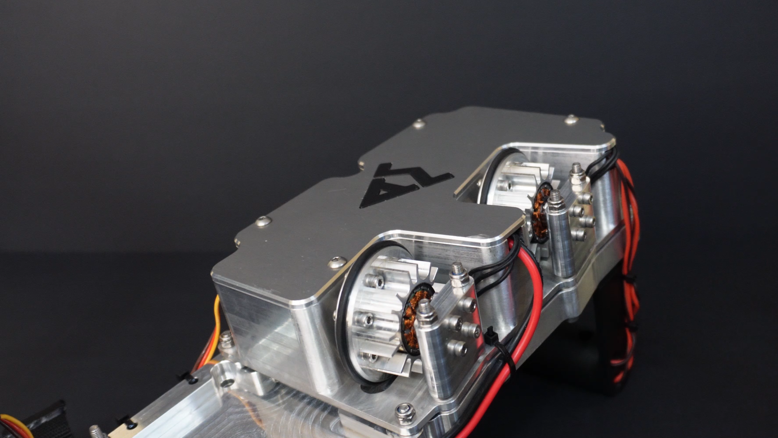
Final Metal Launcher
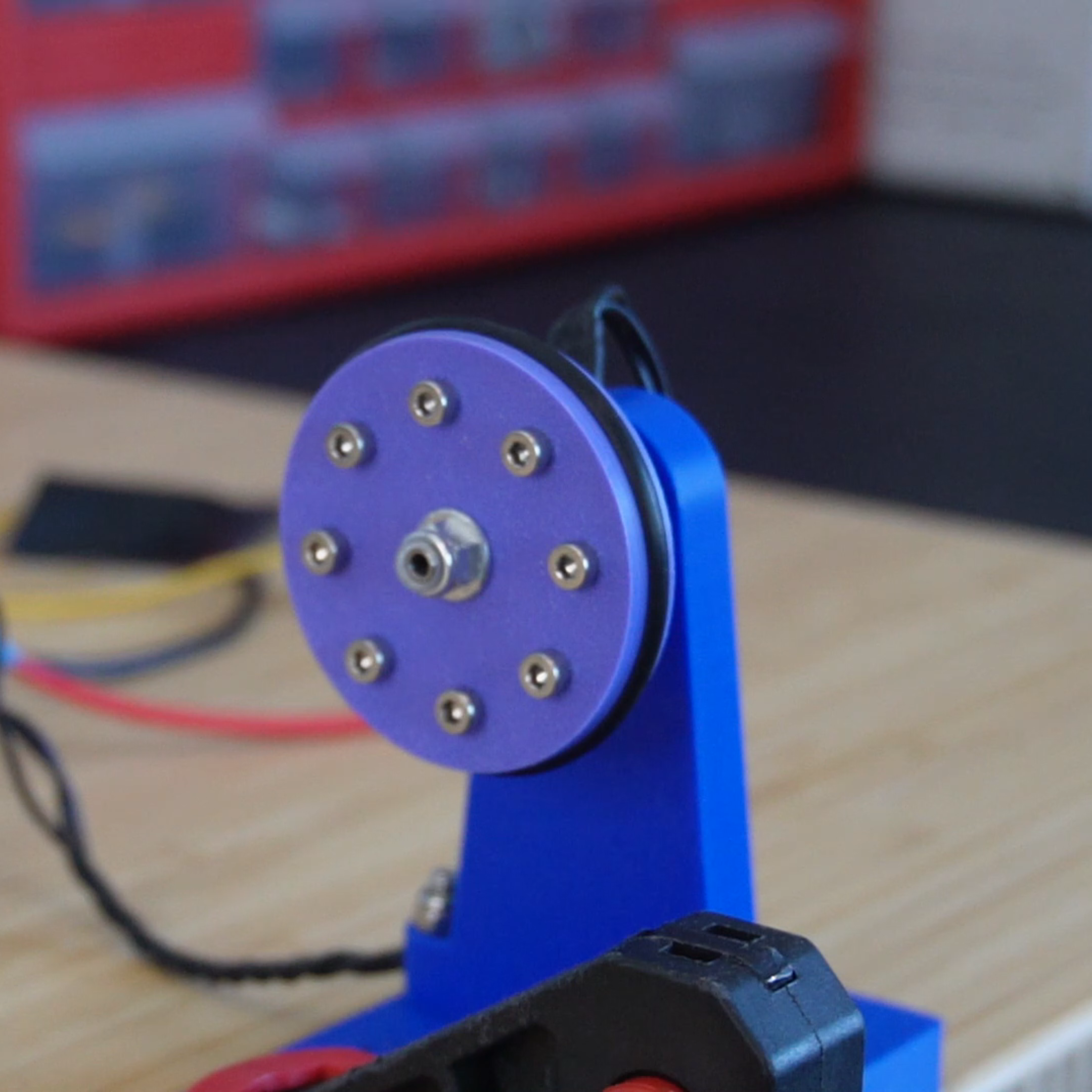
After making the 3D printed wrist mounted CD launcher prototype, I moved on to the final metal version. I go the parts CNC machined in Aluminum 6061 at PCBWay. One important design change I made prior to getting the parts machined was to add fins to the flywheel so that it could additionally function as a heat sink for the motor. During testing, I found that the motors got quite hot. The flywheel-heat sink allows the motors to dissipate some of that heat to the surrounding air. Since aluminum is a great thermal conductor, the fins are extremely effective in dissipating that heat. In addition, because the flywheel is spinning very fast, it generates an airflow that the fins can take advantage of. This further increases the effectiveness of the heat sink in dumping some of that heat into the surrounding air. Adding a heat sink to the flywheel was easily the best design decision that I made in this build. The heat sink worked extremely well. I have personally never seen a heat sink being used to cool motors in this way, so this aspect of the launcher design is quite unique. While most of the launcher was made from metal, I decided to keep the magazine and handle 3D printed simply for the aesthetic.

Results and Future Work
After lots of performance testing, I can conclude that the wrist-mounted CD launcher is a ton of fun to use. It can slice produce, pop balloons, and shatter on impact if shot at a hard object. Overall, I’m fairly happy with the performance of the device, although I was hoping to get much more power from it. Enough power to perhaps shatter glass or stab into a watermelon. This is definitely a project that I will revisit in the future.
One potential design change that I could make in a future iteration would be to use dual coaxial flywheels in each stage. In other words, there would be two flywheels in each stage spinning coaxially and contacting opposite ends of the CD. This setup would firstly allow me to adjust how much spin is imparted on the disc. To generate spin, you would simply spin one of the flywheels in a given stage faster than the other. The bigger the difference is in the speed of the flywheels, the more spin is generated. This setup would remove the need for a rubber strip and an angled flywheel, not that these were an issue. The second benefit of this setup is that it would increase the amount of energy stored by the flywheels, therefore preventing the flywheels from slowing down as much in between shots.
The one pitfall of a dual-coaxial flywheel shooter is that it won’t necessarily lead to a faster projectile. To increase projectile speed, I could do one of a couple of different things. The first obvious one would be to increase the number of flywheel stages. The issue with this approach, and the reason I didn’t do it with this design, is that more stages mean a longer device. The current launcher is already pushing the limit of my arm length. Any additional stages would make it too long. Another way higher CD speeds could be achieved would be to use more powerful motors. Lastly, I could also increase the diameter of the flywheels. This would remove the low-profile aesthetic, but if it allows for a much more powerful shooter, I would definitely consider it.